Remotely Operated underwater Vehicle (ROV)
History:
With my college we had the plan to check if it was possible to build a ROV with normal household products. The result was ROV-1: a PVC tube with on the outside thrusters and on the inside a control system, power supply, motor controllers, camera and a communication system.
Detailed system description:
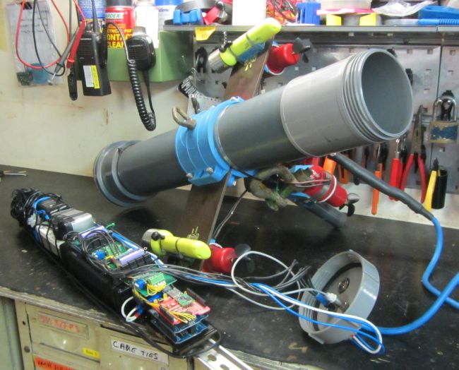
Main body:
The main body of the ROV is made of a 110mm PVCC tube and other appendages. For the window is a plate of Polycarbonate bold in place on a PVCC flange adapter. For the access of the interior and for the cable penetration base, a threaded PVC inspection cover is used with stainless steel cable glands. As mounting for the external components is a bold on T piece with a pipe and plates attached. This T piece holds also the lifting eye.
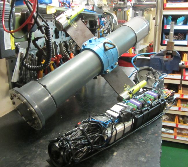
Thrusters:
As base submersible bilge pumps are used. The impeller, impeller housing and suction guard are removed and on the open shaft is a propeller placed. Due to the nature as submersible pump the motor is watertight. The open ends of the cables of all the thrusters are watertight connected to one multicore cable with casting resin.
Umbilical, power supply and communication:
The umbilical is a 2 core PVC extension cable. It is used to transport the 220v power down to the ROV and use the same 220v system to carry a Ethernet over Power (or home bus) signal for communication to and from the ROV. For the communication is on the surface and in the ROV an EoIP adapter with network switch used. Inside the ROV is a 220v to 24v power adapter to convert it down to the value for the thruster motors. Other small voltage regulators are used to generate supplies for the other components. For safety resins on the surface a separation transformer is used.
Control system:
The hard of the control system are Arduino’s. The two systems are connected by Ethernet via Ethernet shields. The Arduino inside the ROV has a compass, pressure sensor, roll and tilt sensor and temperature sensor. This information is send to the surface Arduino when requested. When requested the inside Arduino sets the connected motor controllers and this will turn the propellers. The surface Arduino is used to show the feedback from the sensors on a LCD display and to convert and sent down the input from the connected joysticks.
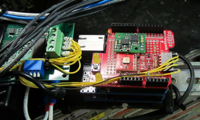
Image system:
To view the live movements of the ROV an IP camera is used and the pictures are available in a web browser. The used camera was not really suitable for the job but the system proves that an IP camera is working. For future use another type of camera will be used (also IP based). As system for taking off-line movies a GoPro2 with underwater housing mounted on the outside is used.
Future:
This project will be continued by my college. He will convert it to a battery powered system with an Ethernet cable as umbilical. I will continue with the ROV-2.
Links:
A movie of the working ROV-1 is to see at: movie.